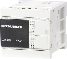
FX3S-14MT/ES | Mitsubishi Electric | FX 3 S series

Call For Order 01843-526720


Reviews & Ratings
Description
Manufacturer : Mitsubishi Electric
FX3S-14MT/ES
FX 3 S series FX 3 S - 14 MT / ES
Arithmetic control method : Stored program iterative calculation method with interrupt instruction
Input / output control method : Batch processing method (when END instruction is executed), I / O refresh command, with pulse catch function
Programming language : Relay symbol method + step ladder method (SFC expressible)
Program memory:-
Maximum memory capacity : 16000 steps Comment, 16000 steps including file register
Internal memory capacity / format : 16000 steps EEPROM (memory backup not required)
Memory cassette (option) : FX3G-EEPROM-32L connectable (32000 step EEPROM) FX3S series can be used up to 16000 steps (program capacity is 4000 steps)
Write function during RUN : Yes (program changeable during sequencer RUN)
Protection function : Keyword protection function / With customer keyword function
Real time clock:-
Clock function : Built-in 1980 to 2079 (with leap year correction) 2-digit / 4-digit year AD changeable, monthly difference ± 45 seconds (25 ° C) ? Note on clock function The current time of the built- It is backed up with. The large capacity condenser (built-in) is fully charged at the energization time of 30 minutes and holds the present value for 10 days.
Types of instructions:-
Basic instruction : · Sequence instruction: 29 pieces · Step ladder instruction: 2 pieces
Application instruction : Application instruction: 116 kinds
Arithmetic processing speed:-
Basic instruction : 0.21 µs / instruction
Application instruction : 0.5 µs to several 100 µs / instructions
Number of input / output points:-
Number of input points : 16 points or less (can not be added)
Number of output points : 14 points or less (can not be added)
Total score : 30 points or less (can not be added)
device:-
I / O relay Input relay : X000 to X017 16 points (octal number) can not be expanded (FX 3 S - 14 M ? corresponds to the range from X 000 to X 007)
Output relay : Y000 to Y015 14 points (octal number) can not be expanded (FX3S - 14M ? corresponds to Y000 ~ Y005 range)
Auxiliary relay For general use 1 : M 0 to M 383 384 points
Keep (EEPROM keep) : M384 to M511 128 points ? Note on keeping area Keep area and nonkeeping area are fixed. (Parameter can not be changed.) In order to reliably keep to EEPROM, it is necessary for the sequencer to be energized for at least 5 consecutive minutes.
For general use 2 : M512 to M1535 1024 points
Special purpose : M8000 to M8511 512 points
State For initial state (EEPROM keep) : S0 to S9 10 points ? Note on keeping area Keep area and nonkeeping area are fixed. (Parameter can not be changed.) In order to reliably keep to EEPROM, it is necessary for the sequencer to be energized for at least 5 consecutive minutes.
Keep (EEPROM keep) : S10 to S127 118 points ? Note on Keep Area Keep area and non-keep area are fixed. (Parameter can not be changed.) In order to reliably keep to EEPROM, it is necessary for the sequencer to be energized for at least 5 consecutive minutes.
For general use : S128 to S255 128 points
Timer (on-delay) 100 ms : T 0 to T 31 63 points (0.1 to 3,276.7 seconds)
100 ms / 10 ms : T32 to T62 31 points (0.1 to 3,276.7 seconds / 0.01 to 327.67 seconds) T32 to T62 (31 points) can be changed to 10 ms timer when M8028 is turned ON
1 ms : T63 to T127 65 points (0.001 to 32.767 seconds)
1 ms integration type : T128 to T131 4 points (0.001 to 32.767 seconds)
100 ms Integration type : T132 to T137 6 points (0.1 to 3,276.7 seconds)
Other : Two internal analog volume can be used as analog timer VR 1: D 8030, VR 2: D 8031 ??2 points (0 to 255)
counter 16 bit up (for general purpose) : C 0 to C 15 16 points (0 to 32,767 counts)
16 bit up (EEPROM keep) : C16 to C31 16 points (0 to 32,767 counts) * Note on keep area Keep area and non-keep area are fixed. (Parameter can not be changed.) In order to reliably keep to EEPROM, it is necessary for the sequencer to be energized for at least 5 consecutive minutes.
32 bit up / down : C200 to C234 35 points (-2, 147, 483, 648 to +2, 147, 483, 647 counts)
High speed counter : [32 bit high-speed up / down (EEPROM keep)] Up to 6 points can be used in C235 to C255 1 phase: 60 kHz, 10 kHz 2 phases: 30 kHz, 5 kHz There are restrictions on points and input frequencies that can be used depending on the conditions used. ? Note on Keep Area Keep area and non-keep area are fixed. (Parameter can not be changed.) In order to reliably keep to EEPROM, it is necessary for the sequencer to be energized for at least 5 consecutive minutes.
Data register (32 bits in pair use) For 16-bit general purpose 1 : D0 to D127 128 points
For 16-bit keep (EEPROM keep) : D128 to D255 128 points ? Note on the keep area Keep area and non-keep area are fixed. (Parameter can not be changed.) In order to reliably keep to EEPROM, it is necessary for the sequencer to be energized for at least 5 consecutive minutes.
For 16-bit general purpose 2 : D256 to D2999 2744 points
File register (EEPROM keep) : D1000 to D2999 2000 points (It can be set to the file register in units of 500 points)
16 bit special use : D 8000 to D 8511 512 points
For 16 bit index : V 0 to V 7, Z 0 to Z 7 16 points
Pointer JUMP, for CALL branch : P0 to P255 256 points (for CJ instruction, CALL instruction, P63 for END jump)
Input interrupt : I 0 ? ? - I 5 ? ? 6 points
Timer interrupt : I6 ?? - I 8 ? ? 3 points
nesting : [For master control] N 0 to N 7 8 points (for MC command)
constant:-
Decimal number (K) : 16 bits: -32,768 to + 32,767 32 bits: -2, 147, 483, 648 to +2, 147, 483, 647
Hexadecimal (H) : 16 bits: 0 to FFFF 32 bits: 0 to FFFFFFFF
Real number (E) : 32 bits: -1.0 × 2 128 to -1.0 × 2 - 126 , 0, 1.0 × 2 - 126 to 1.0 × 2 128 Decimal point representation and exponential representation are possible
Power supply specification :
Rated voltage : AC 100 to 240 V
Voltage tolerance range : AC 85 - 264 V
Rated frequency : 50/60 Hz
Allowable momentary power outage time : Operation continues with an instantaneous blackout of 10 ms or less.
Power supply fuse : 250V 1A
Inrush current : Maximum 15 A 5 ms or less / AC 100 V, 28 A maximum 5 ms or less / AC 200 V
power consumption : In the case of the maximum configuration that can be connected to the 19 W basic unit, this is the value when using 24 VDC service power. It also includes input current (7 mA or 5 mA per point).
24 VDC service power supply : 400 mA
Input specification :
Number of input points : 8 points
Input connection shape : Fixed terminal block (M3 screw)
Input format : Sink / source
Input signal voltage : DC 24 V ± 10%
Input impedance:-
X000 to X007 : 3.3 kO
X010 or later : -
Input signal current:-
X000 to X007 : 7 mA / 24 VDC
X010 or later : -
Input ON sensitivity current:-
X000 to X007 : 4.5 mA or more
X010 or later : -
Input OFF sensitivity current : 1.5 mA or less
Input response time : Approximately 10 ms X000 to X017 have a built-in digital filter and can be changed in 1 ms increments to 0 to 15 ms according to application instructions and D8020. However, when set to 0, it becomes the following. X000, X001: 10 .mu.s X002 to X007: 50 .mu.s X010 to X017: 200 .mu.s
Input signal format : No-voltage contact input At sink input: NPN open collector transistor Source input: PNP open collector transistor
Input circuit insulation : Photocoupler insulation
Input operation display : LED on the panel when driving the photo coupler
Output specification :
Number of output points : 6 points
Output connection shape : Fixed terminal block (M3 screw)
Output type / format : Transistor / sink output
External power supply : DC 5 to 30 V
Maximum load:-
Resistive load : The total load current per 0.5 A / point common should be as follows. Output 1 point / common: 0.5 A or less Output 4 points / common: 0.8 A or less
Inductive load : The total load per 12 W / DC 24 V common should be as follows. Output 1 point / common: 12 W or less / 24 VDC output 4 points / common: 19.2 W or less / 24 VDC
Minimum load : -
Open-circuit leakage current : 0.1 mA or less / DC 30 V
ON voltage : 1.5V or less
Response time:-
OFF ? ON : Y000, Y001: 5 µs or less / 10 mA or more (DC 5 to 24 V) Y002 to Y015: 0.2 ms or less / 200 mA or more (DC 24 V)
ON ? OFF : Y000, Y001: 5 µs or less / 10 mA or more (DC 5 to 24 V) Y002 to Y015: 0.2 ms or less / 200 mA or more (DC 24 V)
Circuit insulation : Photocoupler insulation
Output operation indication : LED on the panel surface when photo coupler is driven
Ambient temperature : 0 to 55 ° C. ··· Operating, -25 to 75 ° C. ····· Save
Relative humidity : 5 to 95% RH (noncondensing) · · · · in operation
Anti-vibration:-
When DIN rail is installed Frequency: 10 to 57 Hz : One amplitude: 0.035 mm X, Y, Z 10 times in each direction (80 minutes in total) The criteria are based on IEC 61131-2
Frequency: 57 to 150 Hz : Acceleration: 4.9 m / s 2 Ten times in each of X, Y, Z directions (total of 80 minutes each) The criterion is based on IEC 61131-2
Direct installation Frequency: 10 to 57 Hz : One amplitude: 0.075 mm X, Y, Z 10 times in each direction (80 minutes in total) The criteria are based on IEC 61131-2
Frequency: 57 to 150 Hz : Acceleration: 9.8 m / s 2 X, Y, Z 10 times in each direction (80 minutes in total) The criteria are based on IEC 61131-2
Impact resistance : 147 m / s 2 , working time 11 ms, criterion for judgment three times in X, Y, Z directions by sine half-wave pulse is according to IEC 61131-2
Noise immunity : Noise voltage with 1,000 Vp-p, noise width 1 µs, rising 1 ns, with noise si
tor with period of 30 to 100 Hz
Withstand voltage : When performing the withstand voltage test, make the voltage between each terminal and the ground terminal of the basic unit with the following voltage. Between the power supply terminal (AC power supply) and the earth terminal: AC 1.5 kV 1 minute DC 24 V service power supply and between the input terminal (24 VDC) and the earth terminal: 500 VAC for 1 min Between the output terminal (transistor)
Insulation resistance : When conducting the insulation resistance test, perform the following voltage between each terminal and the ground terminal of the basic unit. Between the power supply terminal (AC power supply) and the earth terminal: 500 VDC DC insulation resistance meter 5 MO or more DC 24 V service power supply, between the input terminal (24 VDC) and the earth terminal: 500 V DC 500 MO or more with the insulation resistance meter Output terminal Between: 500 MV DC Insulation resistance meter 5 MO or more
ground : Class D grounding (grounding resistance: 100 O or less)
Grounding should be dedicated ground or common ground. Use atmosphere : There is no corrosive property, flammable gas, conductive dust (dust) is not serious
Use altitude : It can not be used under an environment pressurized to 2,000 m or less under atmospheric pressure. It may break down.
Built-in high speed counter function
1 phase 1 count input : [C235, C236] 60 kHz [C237 to C240] 10 kHz [C241] 60 kHz [C242 to C245] 10 kHz When using multiple high-speed counters, make sure that the total of operating frequencies is less than the total frequency.
1 phase 2 count input : [C246] 60 kHz [C248 (OP)] 10 kHz [C247 to C250] 10 kHz When using multiple high-speed counters, make sure that the total of operating frequencies is less than total frequency.
2 phase 2 count input : [C251] 30 kHz [C253 (OP), C252 to C255] 5 kHz When using multiple high-speed counters, ensure that the total operating frequency is less than the total frequency.
Built-in pulse output / positioning function
Number of control axes : Independent 2 axes
Maximum frequency : 100 kHz
Programming language : Sequence program
Corresponding basic unit : Transistor output type basic unit
Pulse output instruction : · Pulse output (PLSY) · Pulse output with acceleration / deceleration (PLSR) Pulse output format: Pulse train (direction controlled by sequence)
Positioning command : · ABS current reading ([D] ABS) · Origin with DOG search [DSZR] · Origin return [ZRN] (No DOG search function) Decelerates with near point DOG: ON and stops at near point DOG: OFF . (It differs from zero point return operation by counting the zero point signal) · Variable speed pulse output [PLSV] · Relative positioning [DRVI] · Absolute positioning [DRVA] Pulse output format: Pulse train + direction
Weight (kg) : 0.3
Dimensions (W x H x D) mm: 60 x 90 x 75
Shipping Weight : 1.3 Kg
Related Product
Product Queries (0)
Login Or Registerto submit your questions to seller
Other Questions
No none asked to seller yet